1. Compute Shader
通常我们的游戏逻辑是跑在CPU上的,但是有一些非常适合并行计算的操作,比如各种粒子运动、流体/布料模拟、大量 AI 行为等,更适合跑在 GPU 上。这是因为 GPU 的核心数量非常多,天然更适合处理能够进行并行的计算。
除了上面所示的一些计算,还有比如图像处理也可以用 Compute Shader,比如某种卷积,某种上色,傅里叶变换等等。
这里值得一提的是,优化这个东西,除非你非常明确这个地方有优化的必要,否则不需要进行过早优化。例如 sin/cos 这些函数在计算的时候,是否用 CPU 计算还是用 GPU 在 Compute Shader 中计算,可能会有重复计算导致的效率上的差别,但是除了计算还有访问显存和内存造成的通信延时等等,而且不同 GPU 的硬件架构也不同,所以在不同类型的机器上效果未必一样。
1.1 Compute Shader 代码
首先,在 Unity 中创建一个 Red.compute 文件,这个后缀所指的文件就是 Compute Shader
#pragma kernel CSMain

RWTexture2D<float4> Result;

[numthreads(8,8,1)]
void CSMain (uint3 id : SV_DispatchThreadID)
{
    Result[id.xy] = float4(1,0,0,1);
}
下面简单介绍下代码做了什么。
#pragma kernel CSMain
是 Compute Shader 的入口声明,CSMain 是 kernel 的名字,表示 GPU 调用时执行的函数,后面你会通过 C# Script 来调用这个函数。
RWTexture2D<float4> Result;
定义了一个 可读写的 2D 纹理(RenderTexture)作为输出,RWTexture2D<float4> 表示每个像素是一个 float4 向量(RGBA 浮点数)。
通过 SetTexture 可以把 Unity 中的 RenderTexture 绑定到这个变量,RW 表示它可以随机写(Random Write),Compute Shader 内可以随意写任意像素。
[numthreads(8,8,1)]
void CSMain (uint3 id : SV_DispatchThreadID)
指定每个线程组(thread group)里包含的线程数,总线程数 = (threadGroupsX * 8, threadGroupsY * 8, threadGroupsZ * 1),这里的具体含义在调用部分会更好理解。
id 是全局线程 ID(不是组内线程 ID),比如 (256, 256, 1) 大小的数据如果通过 numthreads(8,8,1) 处理,id.x 的范围还是从 0 到 255 。
Result[id.xy] = float4(1,0,0,1);
把当前线程对应像素写成 红色。
1.2 调用 Compute Shader
首先获取 kernelID,然后通过 computeShader.Dispatch 语法进行调用。
这里的 threadsX/Y/Z 对应的是 Compute Shader里面的 [numthreads(8,8,1)]。
使用 computeShader.Dispatch 时需要知道总共的 id 范围是 groupSize * groupNumber,这里是 256/8 x 256/8 个线程组。
using UnityEngine;

namespace Scenes.ComputeShaders.Test
{
    public class RenderRedComputeShader: MonoBehaviour
    {
        public ComputeShader computeShader;
        public RenderTexture target;
        public Material material;

        void Start()
        {
            target = new RenderTexture(256, 256, 0);
            target.enableRandomWrite = true;
            target.Create();

            int kernelID = computeShader.FindKernel("CSMain");
            computeShader.SetTexture(kernelID, "Result", target);

            material.SetTexture("_MainTex", target);

            // 启动 GPU 线程:这里是 256/8 x 256/8 个线程组
            computeShader.GetKernelThreadGroupSizes(kernelID, out uint threadsX, out uint threadsY, out _);
            computeShader.Dispatch(kernelID, 256 / (int)threadsX, 256 / (int)threadsY, 1);
        }
    }
}
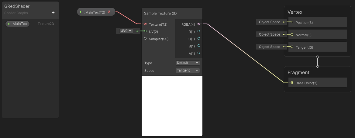
material.SetTexture 同时把这个纹理给绑定到了材质上。这里用到的材质就单纯接收这个纹理并且输出出来。
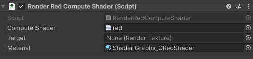
脚本按照下面的方式绑定 Compute Shader 和 Material。
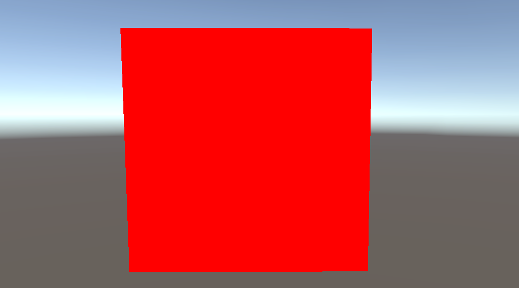
运行游戏后,得到结果:
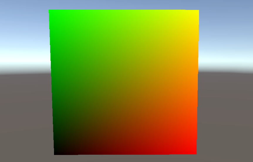
如果我们修改 Compute Shader 改为渐变 2 个通道。
#pragma kernel CSMain

RWTexture2D<float4> Result;

[numthreads(8,8,1)]
void CSMain (uint3 id : SV_DispatchThreadID)
{
    uint width, height;
    Result.GetDimensions(width, height);

    float u = id.x / (float)(width - 1);
    float v = id.y / (float)(height - 1);
    float4 color = float4(u, v, 0, 1);
    Result[id.xy] = color;
}
那么就会得到一张渐变图:
1.3 在 Editor 中使用 Compute Shader
并不是只有在游戏运行的过程中才可以调用 Compute Shader,在 Editor 中同样可以。
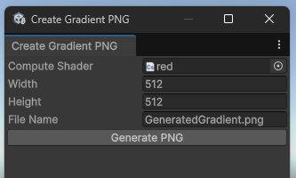
例如我们可以创建这样一个工具:
代码如下:
using UnityEngine;
using UnityEditor;
using System.IO;

public class CreateGradientPNG : EditorWindow
{
    public ComputeShader computeShader;
    public int width = 512;
    public int height = 512;
    public string fileName = "GeneratedGradient.png";

    [MenuItem("Tools/Create Gradient PNG")]
    public static void ShowWindow()
    {
        GetWindow<CreateGradientPNG>("Create Gradient PNG");
    }

    void OnGUI()
    {
        computeShader = (ComputeShader)EditorGUILayout.ObjectField("Compute Shader", computeShader, typeof(ComputeShader), false);
        width = EditorGUILayout.IntField("Width", width);
        height = EditorGUILayout.IntField("Height", height);
        fileName = EditorGUILayout.TextField("File Name", fileName);

        if (GUILayout.Button("Generate PNG"))
        {
            if (computeShader == null)
            {
                Debug.LogError("Please Select Compute Shader");
                return;
            }
            GeneratePNG();
        }
    }

    void GeneratePNG()
    {

        RenderTexture rt = new RenderTexture(width, height, 0, RenderTextureFormat.ARGBFloat);
        rt.enableRandomWrite = true;
        rt.Create();

        int kernel = computeShader.FindKernel("CSMain");
        computeShader.SetTexture(kernel, "Result", rt);

        int threadX = 8;
        int threadY = 8;
        int groupsX = Mathf.CeilToInt(width / (float)threadX);
        int groupsY = Mathf.CeilToInt(height / (float)threadY);
        computeShader.Dispatch(kernel, groupsX, groupsY, 1);

        RenderTexture.active = rt;
        Texture2D tex = new Texture2D(width, height, TextureFormat.RGBAFloat, false);
        tex.ReadPixels(new Rect(0, 0, width, height), 0, 0);
        tex.Apply();
        RenderTexture.active = null;

        // Save to PNG
        byte[] bytes = tex.EncodeToPNG();
        string path = Path.Combine(Application.dataPath, fileName);
        File.WriteAllBytes(path, bytes);
        AssetDatabase.Refresh();

        Debug.Log("PNG 已生成:" + path);

        // Clear RenderTexture
        rt.Release();
        DestroyImmediate(tex);
    }
}
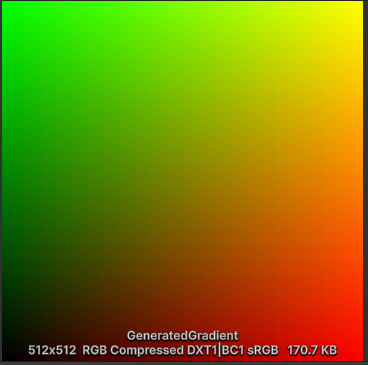
点击后就可以生成 Compute Shader 所计算出的图像:
1.4 GPU 图元类型
如果你写过 Unity Shader 的代码,你应该会很熟悉 Shader 的两个部分:顶点着色器和片元着色器。
但是,通常经历过的顶点着色器是控制的一个三角形的三个点的变化。
在计算机图形学和 GPU 渲染管线中,图元是 GPU 用来描述几何形状的基本单元。GPU 会根据图元类型把顶点数据组合成几何图形,然后进行光栅化、着色等操作。不同的图元类型决定了顶点如何组合成图形。
使用 Graphics.RenderPrimitives 可以绘制各种图元,包括点、线、面、三角形。
rp = new RenderParams(material);
rp.worldBounds = new Bounds(Vector3.zero, 10000*Vector3.one);

Graphics.RenderPrimitives(rp, MeshTopology.Points, 1, particleCount );
// RenderParams The parameters Unity uses to render the primitives.
// topology  Primitive topology (for example, triangles or lines).
// vertexCount	The number of vertices per instance.
// instanceCount	The number of instances to render.
利用 RenderParams 来定义绘制的各种参数,比如用哪种材质,渲染的范围,渲染的摄像机等。
它生成的每个实例的点的位置都是默认的,所以这个 RenderPrimitives 生成的这些点我们需要在材质中的顶点着色器去定义它们实际的位置。
比如下列的 Shader 片段,它在顶点着色器的输出中有一个 PSIZE ,它定义的是点的大小。
struct Attributes
{
    float4 positionOS   : POSITION;
    uint instanceID : SV_InstanceID;
    UNITY_VERTEX_INPUT_INSTANCE_ID
};

struct Varyings
{
    float4 positionHCS  : SV_POSITION;
    float size: PSIZE;
};

Varyings vert(Attributes IN)
{
    Varyings OUT;

    Particle particle = particleBuffer[IN.instanceID];

    OUT.positionHCS = TransformObjectToHClip(particle.position);
    OUT.size = 1;

    return OUT;
}
2. 并行计算
本文的重点主要是在 Compute Shader 如何使用,并不是深入研究算法之类的内容。
案例都来自 Unity 官方的 “Create popular shaders and visual effects with the Universal Render Pipeline”1。
2.1 百万粒子
首先是百万个点,它们将在鼠标周围的位置随机产生,然后倾向于往鼠标方向增加移动速度。
在 Compute Shader 和 粒子的 Shader 中,都会有这么一段:
struct Particle
{
	float3 position;
	float3 velocity;
	float life;
};

// In Compute Shader
RWStructuredBuffer<Particle> particleBuffer;

// In Shader
StructuredBuffer<Particle> particleBuffer;
区别是 Compute Shader 中开启了 RW 随机写入功能,而 Shader 中只需要读取粒子的位置速度和声明周期。
在调用的 C# 脚本中,创建了 ComputeBuffer,ComputeBuffer 是 Unity 提供的一种 GPU 缓冲区对象,主要用于在 C# 脚本和 GPU(Compute Shader / Shader)之间传递数据。它可以理解为一块分配在 GPU 内存上的数组缓冲区,支持高效地存取大量结构化数据。
下面首先创建它,然后分别绑定给两者。
struct Particle
{
    public Vector3 position;
    public Vector3 velocity;
    public float life;
}

void Init()
{
  // initialize the particles
  Particle[] particleArray = new Particle[particleCount];
  // ...
}

// ...
particleBuffer = new ComputeBuffer(particleCount, SIZE_PARTICLE);

particleBuffer.SetData(particleArray);

computeShader.SetBuffer(kernelID, "particleBuffer", particleBuffer);
material.SetBuffer("particleBuffer", particleBuffer);

rp = new RenderParams(material);
rp.worldBounds = new Bounds(Vector3.zero, 10000*Vector3.one);

Graphics.RenderPrimitives(rp, MeshTopology.Points, 1, particleCount);
最后,调用 RenderPrimitives 用指定的 Shader 把这些 ComputeBuffer 所对应的粒子画出来就可以了。
Shader 中根据 instanceID 提取出 particleBuffer 的值,然后做相关变换,然后绘制。这里关联有 GPU 实例化 的相关概念,建议查阅下资料。SV_InstanceID 就是用于将 instanceID 输入标记为GPU的实例ID。UNITY_VERTEX_INPUT_INSTANCE_ID 直接理解为一种需要设置的宏就可以了,实际上它展开就等价于设置instanceID : SV_InstanceID,这里实际上不起效果。
struct Attributes
{
    float4 positionOS   : POSITION;
    uint instanceID : SV_InstanceID;
    UNITY_VERTEX_INPUT_INSTANCE_ID
};

Varyings vert(Attributes IN)
{
    Varyings OUT;

    Particle particle = particleBuffer[IN.instanceID];

    float lerpVal = particle.life * 0.25f;
    OUT.color = half4(1.0f - lerpVal+0.1, lerpVal+0.1, 1.0f, lerpVal);

    OUT.positionHCS = TransformObjectToHClip(particle.position);

    OUT.size = _PointSize;

    return OUT;
}

half4 frag(Varyings IN) : SV_Target
{
    return IN.color;
}
2.2 鸟群算法 Boids
Boids(鸟群算法)是 Craig Reynolds 在 1986 年提出的一种模拟群体行为的算法,用来再现鸟群、鱼群等群体运动。它的核心是基于个体(Boid)的局部规则,而不是全局控制。主要有三条基本规则:
分离(Separation) 避免和邻近个体距离太近,防止碰撞。 个体遍历附近的单位,根据距离计算斥力。
对齐(Alignment) 尽量朝着邻居平均的方向飞行,使群体保持一致的移动趋势。 个体遍历附近的单位,将方向渐渐对齐附近单位的平均方向。
凝聚(Cohesion) 朝向邻居的中心靠拢,保持群体的整体性。 个体遍历附近的单位计算它们的几何中心,将位置渐渐对齐这个中心点。
这三条规则结合起来,就能产生出自然的群体行为效果,而无需全局规划。当然,这三条基本原则实现的时候,主要通过这三条规则调整一个综合目标方向,然后个体渐渐朝向这个目标方向,同时根据时间来计算在这个方向上的位移。
在这个演示中,共享的是位置和速度,在 Compute Shader 中计算出这两个值后,再在 Shader 中通过矩阵变换顶点,渲染出来。
struct Boid
{
	float3 position;
	float3 direction;
	float noise_offset;
};

RWStructuredBuffer<Boid> boidsBuffer;
算法计算上,对每个点都会遍历其他所有点,然后计算 Boids 算法对应的三个规则,计算出方向和位移。
[numthreads(256,1,1)]
void CSMain (uint3 id : SV_DispatchThreadID)
{
	Boid boid = boidsBuffer[id.x];

	float3 separation = 0;
	float3 alignment = 0;
	float3 cohesion = flockPosition;

	uint nearbyCount = 1; // Add self that is ignored in loop

	for (uint i = 0; i < (uint)boidsCount; i++) {
		if (i == id.x) continue;

		Boid tempBoid = boidsBuffer[i];

		float dist = distance(boid.position, tempBoid.position);

		if (dist < neighbourDistance)
		{
			float3 offset = boid.position - tempBoid.position;
			dist = max(dist, 0.000001);//Avoid division by zero
			separation += offset * (1.0/dist - 1.0/neighbourDistance);

			alignment += tempBoid.direction;
			cohesion += tempBoid.position;

			nearbyCount += 1;
		}
	}

	float avg = 1.0 / nearbyCount;
	alignment *= avg;
	cohesion *= avg;
	cohesion = normalize(cohesion - boid.position);

	float3 direction = alignment + separation + cohesion;

	boid.direction = lerp(normalize(boid.direction), direction,  0.01);

	boid.position += (boid.direction * boidSpeed * deltaTime);

	boidsBuffer[id.x] = boid;
}
在 Shader 中依然是通过读取 ComputeBuffer 里的值,去移动顶点(或者构建一个旋转移动矩阵),之后就都是正常的渲染过程了。
float4x4 create_matrix(float3 pos, float3 dir, float3 up) {
    float3 zaxis = normalize(dir);
    float3 xaxis = normalize(cross(up, zaxis));
    float3 yaxis = cross(zaxis, xaxis);
    return float4x4(
        xaxis.x, yaxis.x, zaxis.x, pos.x,
        xaxis.y, yaxis.y, zaxis.y, pos.y,
        xaxis.z, yaxis.z, zaxis.z, pos.z,
        0, 0, 0, 1
    );
}

Boid boid = boidsBuffer[input.instanceID];

float4x4 mat = create_matrix(boid.position, boid.direction, float3(0.0, 1.0, 0.0));
然后接下来实践上的关键是,如何绘制这么多 Mesh 呢?
利用 Graphics.RenderMeshIndirect,设置好渲染的数量和材质即可。RenderMeshIndirect 适合大规模、GPU 决定绘制,可以做真正的大量粒子、草、GPU LOD,CPU 负担极小。与之相对的还有个 DrawMeshInstanced,每次渲染要传递进去矩阵,不太方便。
argsBuffer = new GraphicsBuffer(GraphicsBuffer.Target.IndirectArguments, 1, GraphicsBuffer.IndirectDrawIndexedArgs.size);

GraphicsBuffer.IndirectDrawIndexedArgs[] data = new GraphicsBuffer.IndirectDrawIndexedArgs[1];

// The number of vertex indices per instance.
data[0].indexCountPerInstance = boidMesh.GetIndexCount(0);

// The number of instances to render.
data[0].instanceCount = (uint)numOfBoids;
argsBuffer.SetData(data);

renderParams = new RenderParams(boidMaterial);
renderParams.worldBounds = new Bounds(Vector3.zero, Vector3.one * 1000);

Graphics.RenderMeshIndirect(renderParams, boidMesh, argsBuffer);
2.3 带有动画的单位
在 Compute Shader 中依然还是计算顶点位置,但是还多计算一个动画帧的值,根据速度、时间来插值。
boid.frame = boid.frame + velocity * deltaTime * boidFrameSpeed;
if (boid.frame >= numOfFrames) boid.frame -= numOfFrames;
同时在 Shader 中多一个 vertexAnimation 表示顶点动画,它是
struct Boid
{
    float3 position;
    float3 direction;
    float noise_offset;
    float frame;
    float3 padding;
};

StructuredBuffer<Boid> boidsBuffer;
StructuredBuffer<float4> vertexAnimation;
应用的时候是读取 vertexAnimation 来得到应用动画后的位置,之后再进行 MVP。
#ifdef FRAME_INTERPOLATION
    uint next = boid.frame + 1;
    if (next >= numOfFrames) next = 0;
    float frameInterpolation = frac(boidsBuffer[input.instanceID].frame);
    input.positionOS.xyz = lerp(vertexAnimation[input.vertexID * numOfFrames + boid.frame], vertexAnimation[input.vertexID * numOfFrames + next], frameInterpolation);
#else
    input.positionOS.xyz = vertexAnimation[input.vertexID * numOfFrames + boid.frame];
#endif
这个系统里 Animator 的作用在初始化阶段就结束了,运行时 Boid 已经不再依赖 Unity 动画系统,而是完全依赖 GPU Buffer 中的烘焙顶点动画 + Boid 数据 来控制移动和播放动画。
将蒙皮网格中的网格提取出来。
boidSMR = boidObject.GetComponentInChildren<SkinnedMeshRenderer>();

boidMesh = boidSMR.sharedMesh;
烘焙然后存储每个节点的位置。
animator.Play(aniStateInfo.shortNameHash, iLayer, sampleTime);
animator.Update(0f);

boidSMR.BakeMesh(bakedMesh);

for(int j = 0; j < vertexCount; j++)
{
    Vector4 vertex = bakedMesh.vertices[j];
    vertex.w = 1;
    vertexAnimationData[(j * numOfFrames) +  i] = vertex;
}
最后传递给 Shader 这个动画网格的变化坐标
vertexAnimationBuffer.SetData(vertexAnimationData);
boidMaterial.SetBuffer("vertexAnimation", vertexAnimationBuffer);
Unity, Create popular shaders and visual effects with the Universal Render Pipeline, https://unity.com/resources/create-shaders-visual-effects-urp-unity-6 ↩︎
Unity, URP Cookbook: Compute shaders - Part 1: Particle fun, https://www.youtube.com/watch?v=omZap7XHxKc&ab_channel=Unity ↩︎
NikLever, GitHub, https://github.com/NikLever/Unity-URP-Cookbook-Unity6 ↩︎